Pyure MVP16 Application Operating Guide
Pyure MVP16™ Application Operating Guide
This guide provides a simple, user-friendly overview of the Pyure MVP16 application interface used in operating a standalone MVP16 system. It outlines each screen and describes how users interact with individual fields to monitor, configure, and maintain the purification system. Designed to support system setup and ongoing operation, the guide helps users understand the application's core functions and how each feature contributes to effective air and surface purification management.
Main Screen
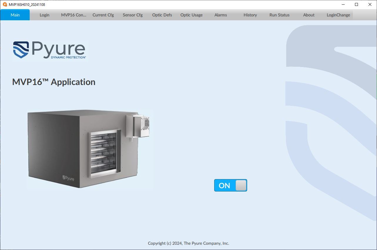
The Main screen presents multiple tabs across the top of the application. The tabs presented will depend on the user logged into the system. Selecting a tab will navigate the application to the particular screen.
The ON/OFF Switch Enables the MVP16 unit when in the ON position and Disables the Unit from processing when in the OFF position.
MVP16 Configuration Screen
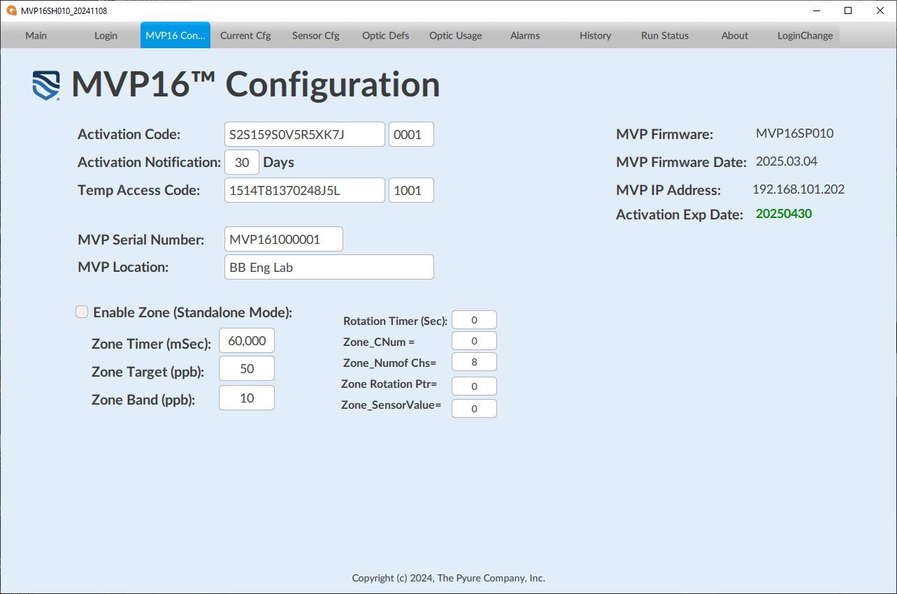
The MVP16 Configuration Screen allows the Administrator or Engineer user to enter various configuration parameters and operational information for the system as follows:
Activation Code: Enter the activation code from Pyure to start the system. If the code is valid, it will show an expiration date in green.
Activation Expiration: Displays the activation expiration date generated by the activation code.
Activation Notification: Enter how many days in advance you want to receive a warning before the activation expires.
Temp Access Code: This temporary activation code is only valid for one day. This code allows a user to change various parameters that would typically not be permitted by the user's permissions.
MVP Serial Number: This should contain the serial number of the MVP16 unit, which must match the serial number on the MVP16 unit's product label.
MVP Location: A free-form text field utilized to document and identify the location of the MVP16 unit.
MVP Firmware: Displays the current firmware version of the MVP16 application.
MVP Firmware Date: Displays the current firmware date of the MVP16 unit application.
MVP IP Address: Displays the current IP address of the MVP16 unit.
Enable Zone (Standalone Mode): Enables/Disables the MVP16 unit to automatically control the Optic Channels of the MVP16 unit based on the Zone Configuration parameters.
Zone Timer (mSec): This setting sets the control system's update rate when Auto Mode is enabled. The rate is in milliseconds.
Zone Target (ppb): Sets the target Total Oxidant Level of the MVP16 control system when the Zone is enabled (in Standalone Mode).
Zone Band (ppb): Sets the Control Band around the Target level of the MVP16 control system when the Auto Mode is enabled.
Zone Rotation Channel: Sets and shows the current starting channel pointer used for the optic channel rotation. This number is incremented when the Rotation Timer expires.
Rotation Timer (Sec): This setting sets the Optic Channel rotation timer (in seconds). When this timer expires, the Optic channels are 'rotated'.
Zone CNum: Displays the number of Channels Active.
Zone Numof Chs: Displays the total number of Optic Channels of the MVP16 unit enabled.
Zone Rotation Ptr: Sets and shows the current starting channel pointer used for the optic channel rotation. This number is incremented when the Rotation Timer expires.
Zone_SensorValue: Displays the Sensor Value (after sensor scaling and corrections).
Current Configuration Screen
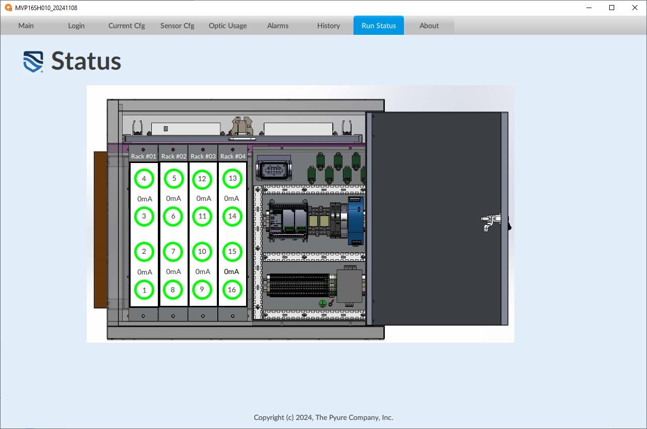
The zone configuration screen allows the user to enter various configuration parameters for the optic racks as follows:
OPTIC RACK Table: This table is used to set up the parameters for the Optic Racks. It displays the Rack Numbers and the OPTIC BANK (or channel) to be configured.
- Max OFF Limit (mA): Sets the maximum current that should be seen when an Optic Channel is turned OFF. (Note: This is used to check for a Stuck Relay condition.)
- Min ON Limit (mA): Sets the Minimum current that should be seen when an Optic Channel is turned ON. (Note: Used to check for failing optics)
- Current Value (mA): Displays the electrical current in milli-Amps of the Optic Channel.
OFF Delay (mSec): Time delay used to determine an error condition when an Optic Channel is turned OFF.
ON Delay (mSec): Time delay used to determine an error condition when an Optic Channel is turned ON. (Used to allow the Optic Channel to stabilize its electrical current level for error detection).

Sensor Configuration Screen
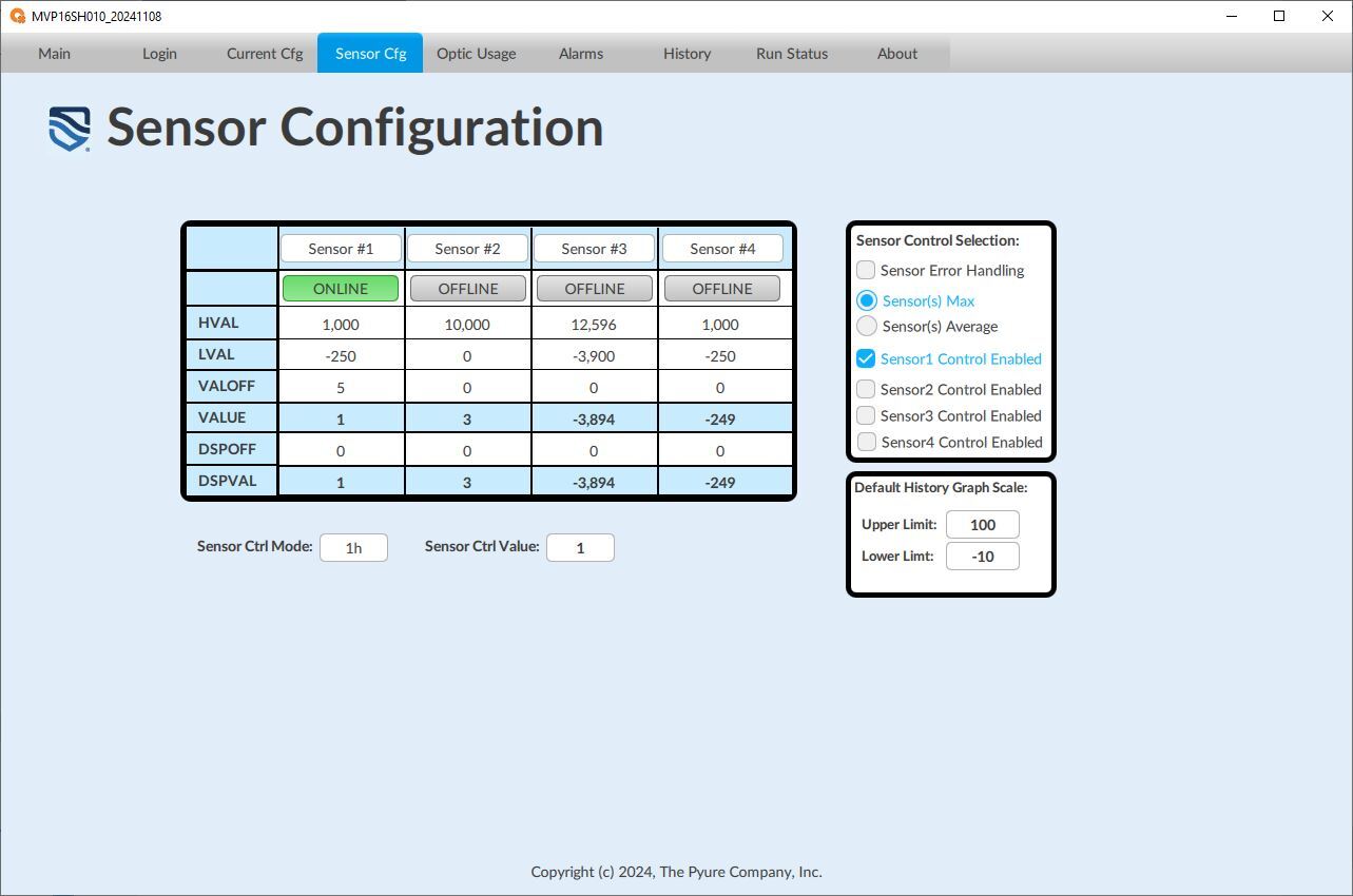
The Sensor Configuration screen allows the user to enter various configuration parameters for the Sensors connected to the MVP16 unit as follows:
Sensor Configuration Table: This table is used to set the parameters for Sensors that are directly wired to the MVP16's analog input channels.
- OnLine/Offline: Enables/Disables the Sensor(s) to be utilized in controlling the MVP16 unit.
- HVAL: Used to set the maximum sensor scaling factor
- LVAL: Used to set the minimum sensor scaling factor
- VALOFF: Used to set the control system's correction/adjustment scaling factor.
- VALUE: Displays the Sensor Value (after sensor scaling and corrections) used in the control system.
- DSPOFF: Used to set the correction/adjustment scaling factor for the sensor display.
- DSPVAL: Displays the sensor value (after sensor scaling and corrections).
Note: All sensors enabled for control should be scaled to parts-per-million (ppb).
Sensor Control Selection Table: This table is used to set up the mode of the sensors and enable the sensors to be used for control in the selected zone.
- Sensor Error Handling: When checked, this option permits one or more sensors to be in error and still allows the control system to continue. When unchecked, if any sensor goes into error, the whole Selected Zone will be disabled.
- Sensor(s) Max: Will utilize the Maximum value of all of the Sensors selected to be utilized by the control system.
- Sensor(s) Average: Will utilize the Average value of all of the Sensors selected to be used by the control system.
- Sensor#1 through Sensor#4 Enabled: Selects the sensors utilized by the Selected Zone's control.
Sensor Ctrl Mode: Displays the result of the sensor configuration selected in the Sensor Control Selection Table.
Sensor Ctrl Value: The resultant control value of the Sensor(s) and mode selected for the Zone.
Default History Graph Scale: Selects the Upper and Lower Limits for the Sensor Display Graph.
Note: Not all Sensors mapped to a Zone need to be utilized for control. The system will record/store all sensors mapped to the Zone.
Optic Definitions Screen
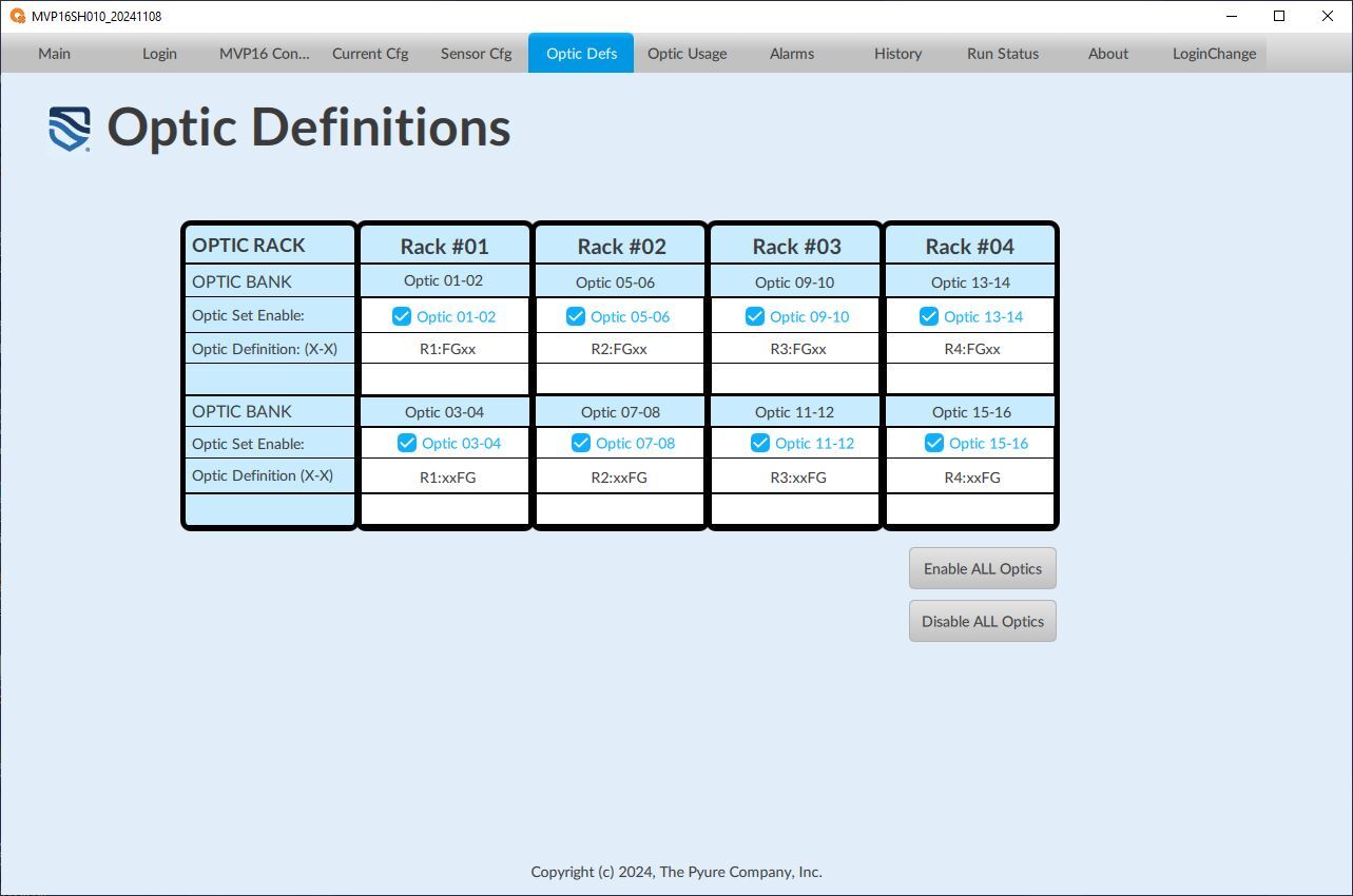
The MVP16 Optic Definitions screen allows the user to enter various configuration parameters and operational information for each selected Optic Channel as follows:
Optic Set Enable: Enable/Disables the Optic Channels set to be utilized by the MVP16 control system.
Optic Definitions (X-X): A free-form text field utilized to document and identify the Rack location as well as the optic type of the Optic Channel. (Note: The format should be as shown. In the example screen, Rack #01, Optic 01 & 03 have an ‘F’ type optic type, and Optic 02 & 04 have a 'G' type optic type.
Enable ALL Optics: A quick way to enable ALL Optic Channels.
Disable ALL Optics: A quick way to disable ALL Optic Channels.
Optic Usage Screen
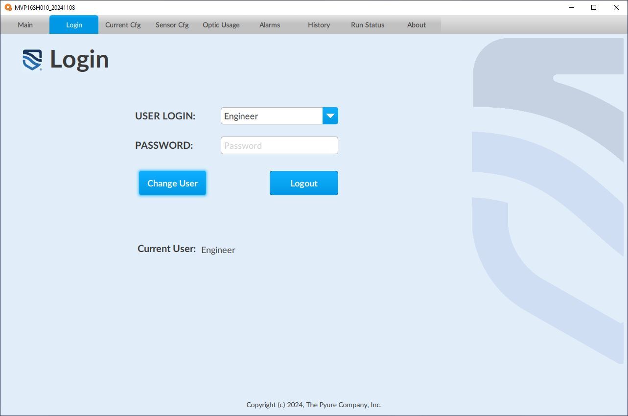
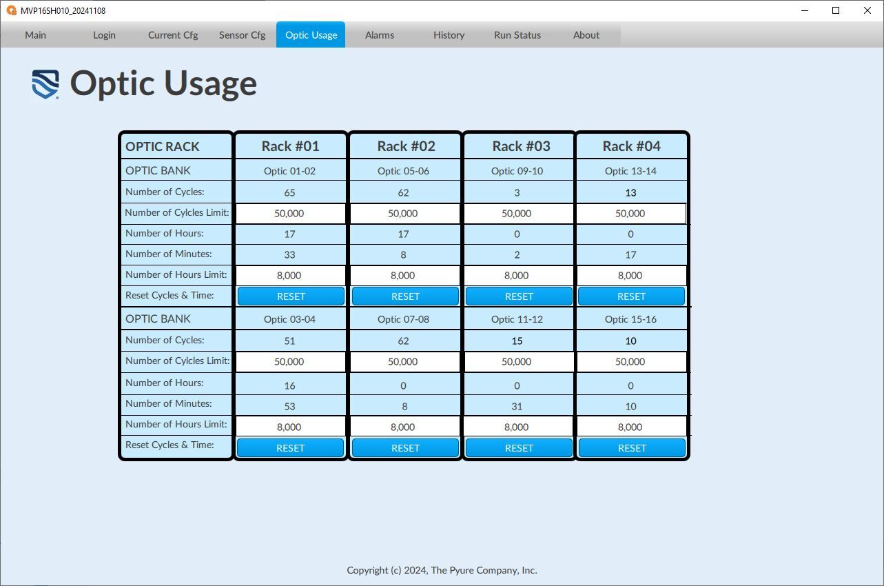
The Optic Usage screen displays the operating conditions of the Optic Channels on the MVP16™ unit.
Optic Usage Table:
- # of Cycles: Displays the number of Cycles (ON/OFF) of the Optic Channel
- # of Cycles Limit: This setting sets the number of Cycles Limit of the Optic Channel, which, when exceeded, will raise a System Warning Alarm Message.
- # of Hours:Mins: Displays the number of Hours and Minutes the Optic Channel has been active.
- # of Hours Limit: Sets the Optic Channel's hour limit, which, when exceeded, will raise a System—+Warning Alarm Message.
- Reset Cycles/Time: Resets the Cycle Count and Hours/Minutes of the Optic Channel.
Alarms History Screen
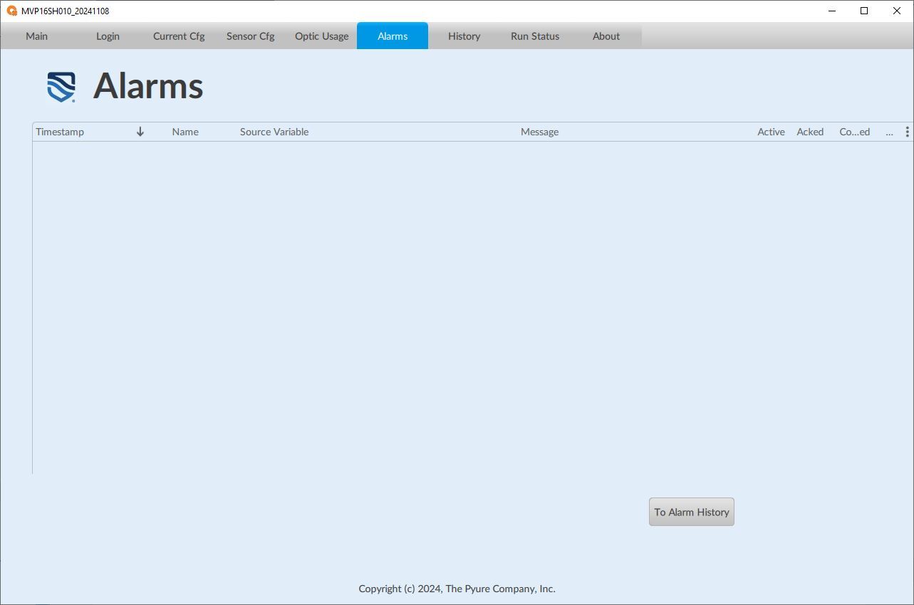
Displays the past alarms with time/date stamps showing when they occurred.
From/To: Allows the User to select the alarm period to be displayed.
Refresh Button: Refreshes the screen once the From/To date and time have been set.
Export Log Button: Saves the alarms to a text file.
To Alarm Acks Button: Navigates to the Active Alarm screen.

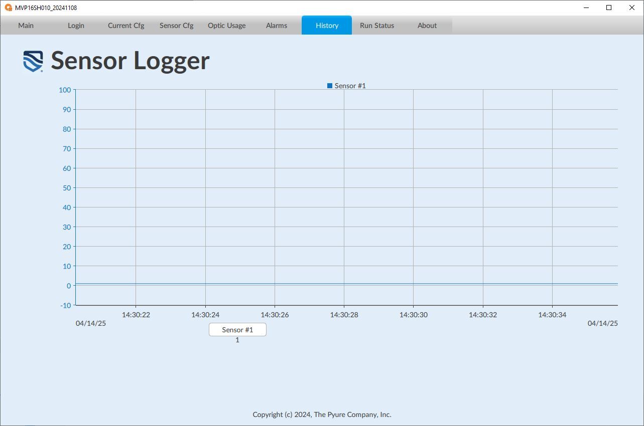
Sensor Logger Screen
The Sensor Logger screen enables the user to display Sensor Data. (Note: This screen is interactive in that the USER can scroll different time periods and change the sensor scale of the graph. The USER can select different points on the graph.... which will then display the Date/Time and Sensor Value(s) of the point selected).
About Screen
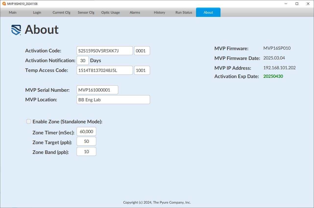
The About screen allows the user to enter various operational information and configuration parameters for the system as follows:
Activation Code: Enter the activation code from Pyure to start the system. If the code is valid, it will show an expiration date in green.
Activation Exp Date: Displays the activation expiration date generated by the activation code.
Activation Notification: Specify how many days in advance you want to receive a warning before the activation expires.
Temp Access Code: This temporary activation code is valid for one day. This code allows a user to change various parameters that would typically not be permitted by the user's permissions.
MVP Serial Number: This should contain the serial number of the MVP16 unit, which must match the serial number on the MVP16's product label.
MVP Location: A free-form text field utilized to document and identify the location of the MVP16 unit.
MVP Firmware: Displays the current firmware version of the IMVP16 unit.
MVP Firmware Date: Displays the current firmware date of the MVP16 application.
MVP IP Address: Displays the current IP address of the MVP16 unit.
Enable Zone (Standalone Mode): Enables/Disables the MVP16 unit to automatically control the Optic Channels of the MVP16 unit based on the Zone Configuration parameters.
Zone Timer (mSec): This setting sets the control system's update rate when Auto Mode is enabled. The rate is in milliseconds.
Zone Target (ppb): This setting sets the target Total Oxidant Level of the MVP16 control system when the Zone is enabled (in Standalone Mode).
Zone Band (ppb): Sets the Control Band around the Target level of the MVP16 control system when the Auto Mode is enabled.
Copyright 2025, The Pyure Company
MVP16 is a trademark of The Pyure Company
Boynton Beach, FL 33426 USA
Document # MVP16LA000
07/28/2025

