Pyure Insight Edge Application Operating Guide
Pyure Insight® Edge Application Operating Guide
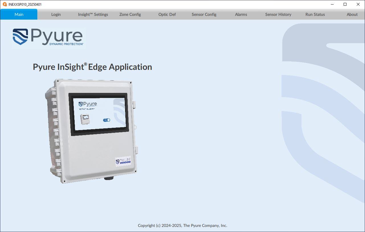
This guide provides a simple, user-friendly overview of the Pyure Insight Edge application interface. It outlines each screen and describes how users interact with individual fields to monitor, configure, and maintain the purification system. Designed to support system setup and ongoing operation, the guide helps users understand the application's core functions and how each feature contributes to effective air and surface purification management.
The Insight Edge application is part of the Insight Edge system complete air and surface purification solution. The system includes these main parts:
Insight Edge Application
This is the software that powers the controller. It is used to configure the system, monitor performance, and manage how each purification device responds to sensor data. The user can access multiple system-level menus through this application, which facilitates device management, configuration, UV optic and sensor alarms, performance monitoring, and system maintenance.
Insight Edge Controller
This is the hardware device that connects to sensors and Pyure equipment. It collects real-time sensor data and tells the purification device how to operate based on that data. The controller may include an optional touchscreen (HMI) for user interaction. It runs the Insight Edge application.
Insight Edge System
This refers to the entire setup when a Pyure air purification device (or multiple devices), one or more sensors, and an Insight Edge controller are connected and working together. The system monitors air quality and automatically adjusts purification levels for optimal performance.
Insight Settings Screen
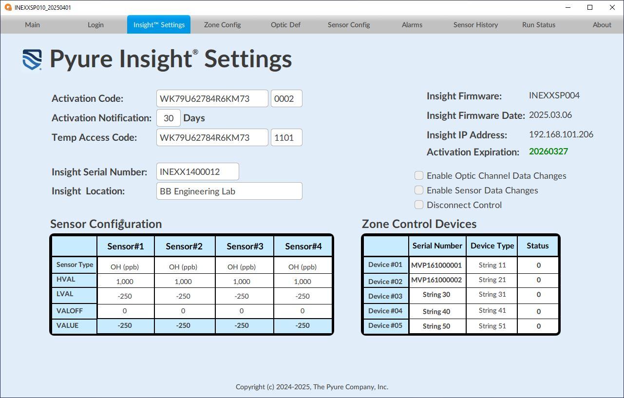
The Insight Settings screen allows the user to enter various configuration parameters and operational information for the system as follows:
Activation Code: Enter the activation code from Pyure to start the system. If the code is valid, it will show an expiration date in green.
Activation Expiration: Displays the activation expiration date generated by the activation code.
Activation Notification: Enter how many days in advance you want to receive a warning before the activation expires.
Temp Access Code: This temporary activation code is only valid for one day. This code allows a user to change various parameters that would typically not be permitted by the user's permissions.
Insight Serial Number: This should contain the serial number of the Insight Edge controller, which must match the serial number on the controller's product label.
Insight Location: A free-form text field utilized to document and identify the location of the Insight Edge controller.
Insight Edge Firmware: Displays the current firmware version of the Insight Edge controller application.
Insight Firmware Date: Displays the current firmware date of the Insight Edge controller application.
Insight IP Address: Displays the current IP address of the Insight Edge controller.
Insight Sensor Configuration Table: Used to set the parameters for sensors directly wired to the Insight Edge controller's analog input channels.
- Sensor Type: Used to describe the sensor type and the measurement unit (i.e., ppb, ppm, etc.).
- HVAL: Used to set the maximum sensor scaling factor.
- LVAL: Used to set the minimum sensor scaling factor.
- VALOFF: Used to set the correction/adjustment scaling factor.
- VALUE: Displays the sensor value (after sensor scaling and corrections).
Zone Control Devices Table: Displays mapped devices utilized by the Insight Edge controller. This enables the controller to report device-level statuses in addition to the mapped optic channel and/or sensors that may be part of the device.
- Serial Number: Displays the serial number of the mapped device.
- Device Type: Displays the model/type of the mapped device.
- Status: Displays the mapped device status code. The system interprets this status code and displays the warning and/or error messages associated with the mapped device.
Zone Config Screen
The zone configuration screen allows the user to enter various configuration parameters and operational information for each selected zone as follows:
Zone Number Selected: Enter the zone number for the zone to be displayed/configured.
Total Zones Defined: Displays the total number of zones defined and controlled by the Insight Edge controller.
Number of Channels: Displays the total number of optic channels mapped to the selected zone.
Number of Sensors: Displays the total number of sensors mapped to the selected zone.
Zone OnLine: Enables/Disables the selected zone to be under the control of the Insight Edge controller.
Zone Control (Auto Mode): Enables the controller to automatically control the optic channels of the selected zone based on the zone configuration parameters.
Non-Aggressive Control: Enables the control system to utilize a less aggressive control algorithm.
Zone Location: A free-form text field utilized to document and identify the location of the selected zone.
Zone Target (ppb): Sets the control system's target total oxidant level when the auto mode is enabled. Note: All sensors selected for control should be scaled to parts-per-billion (ppb).
Zone Band (ppb): Sets the control band around the control system's target level when the auto mode is enabled.
Zone Timer (mSec): Sets the control system's update rate when the auto mode is enabled. The rate is in milliseconds.
Zone Rotation Channel: Sets and displays the current starting channel point for optic channel rotation. The number increases when the rotation timer expires.
Rotation Timer (mSec): Sets the optic channel rotation timer (in milliseconds). The optic channels rotate when this timer expires.
Sensor Control Selection Table: Used to set up the mode of the sensors and enable the sensors used for control in the selected zone.
- Sensor Error Handling: When checked, this option permits one or more sensors to be in error and still allows the control system to continue. When unchecked, if any sensor goes in error, the whole selected zone will be disabled.
- Sensor(s) Max: The control system will use the maximum value of all selected sensors.
- Sensor(s) Average: The control system will use the average value of all selected sensors.
- Sensor #1 - #8 Zone Enabled: Selects the sensors the selected zone's control utilizes.
- Sensor Control Value: The control value determined by the selected sensors and mode for the chosen zone.
Zone Sensor Values Table: Shows the sensors that have been enabled (in Green), the type of sensor, and the current value of the sensor(s) in the selected zone. Note: Not all sensors mapped to a zone need to be utilized for control. The system will record/store all sensors mapped to the zone.
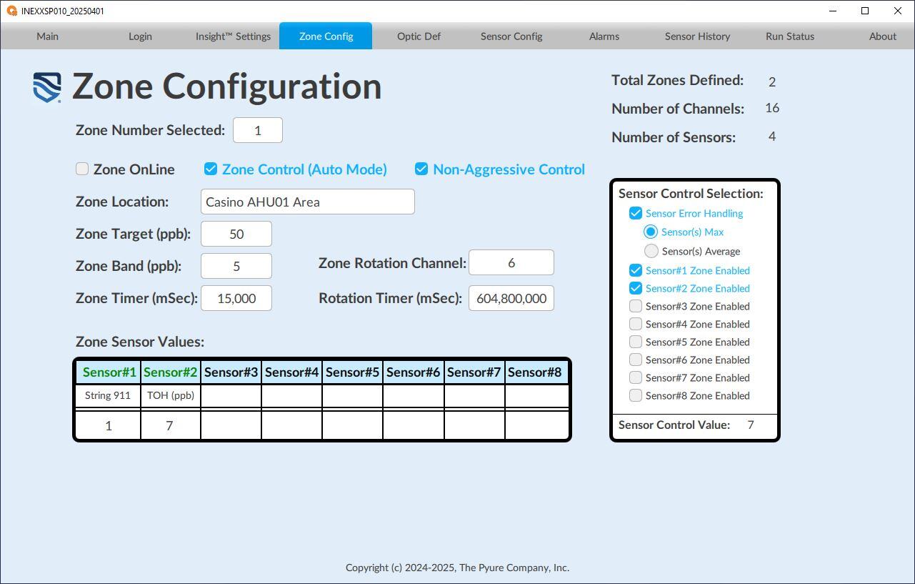
Optic Definitions Screen
The optic definitions screen allows users to input configuration settings and operational details for each optic channel mapped to the selected zone.
Zone Number Selected: Enter the zone number for the zone to be displayed/configured.
Total Zones Defined: Displays the total number of zones defined and controlled by the Insight Edge controller.
Number of Channels: Displays the total number of optic channels mapped to the selected zone.
Number of Sensors: Displays the total number of sensors mapped to the selected zone.
Channel #01 - #08, Channel #09 - #16, Channel #17 - #24 Tabs: Selects the optic channels to be displayed and configured in the selected zone.
- Ch#xx ... Ch#xx: Displays the optic channel numbers of the selected tab.
- On/Offline: Select if the optic channel is ONLINE or OFFLINE.
- Serial Number: Displays the serial number of the mapped optic channel.
- Location: A free-form text field utilized to document and identify the location of the mapped optic channel.
- Type [R#:] OOxx : A free-form text field used to document and identify the location of the mapped optic channel. Note: The format should be as shown if mapped from a rack. In the example screen, optic channel #01 is mapped from an MVP16 unit with serial number MVP160000001, rack #1, with two 'F' type optics in MVP16 optic #01 and #02 of the rack.
- # of Cycles: Displays the number of cycles (ON/OFF) of the optic channel
- # of Cycles Limit: Sets the cycle limit for the optic channel. If this limit is exceeded, a warning alarm will be raised.
- # of Hours:Mins: Displays how long the optic channel has been active in hours and minutes.
- # of Hours Limit: Sets the maximum hours the optic channel can be active. If this limit is exceeded, a warning alarm message will be raised.
- Reset Cycles/Time: Resets the optic channel's cycle count, hours, and minutes.
- Current MaxOFF: Sets the maximum current that should be seen when an optic channel is turned off. Note: This is used to check for a stuck relay condition.
- Current MinON: Sets the minimum current that should be seen when an optic channel is turned on. Note: Used to check for failing optics.
- Current (mA): Displays the electrical current in milli-amps of the optic channel.
- Status Code: Displays the status code of the mapped optic channel.
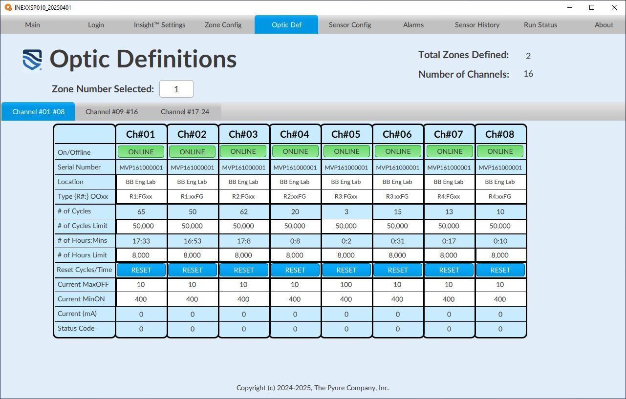
Sensor Config Screen
The sensor configuration screen allows users to input settings and operational details for each sensor mapped to the chosen zone as follows:
Zone Number Selected: Enter the zone number for the zone to be displayed/configured.
Total Zones Defined: Displays the total number of zones defined and controlled by the Insight Edge controller.
Number of Channels: Displays the total number of optic channels mapped to the selected zone.
Number of Sensors: Displays the total number of sensors mapped to the selected zone.
Sensor Table:
Sensor #1 - #8: Displays/Sets information on the sensors in the selected zone.
On/Offline: Select if the sensor is ONLINE or OFFLINE in the selected zone.
Serial Number: Displays the serial number of the mapped sensor (/or/ Serial Number of the Device where the Sensor is connected).
- Location: A free-form text field utilized to document and identify the location of the mapped sensor.
- Sensor Type: A free-form text field is utilized to document and identify the sensor type and unit of measurement of the mapped sensor.
- VALUE: Displays the value of the sensor.
- CTRLOFF: Sets the control offset to make corrections to the sensor value used by the control system.
- CTRLVAL: Displays the corrected sensor value used by the control system.
- DSPOFF: Sets the display offset to make corrections to the sensor value displayed by the system.
- DSPVAL: Displays the corrected sensor value shown by the system.
- STATUS: Displays the status code of the mapped sensor.
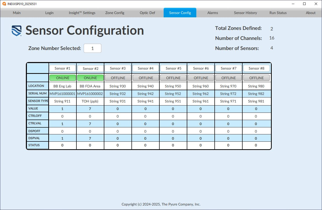
Alarms History Screen
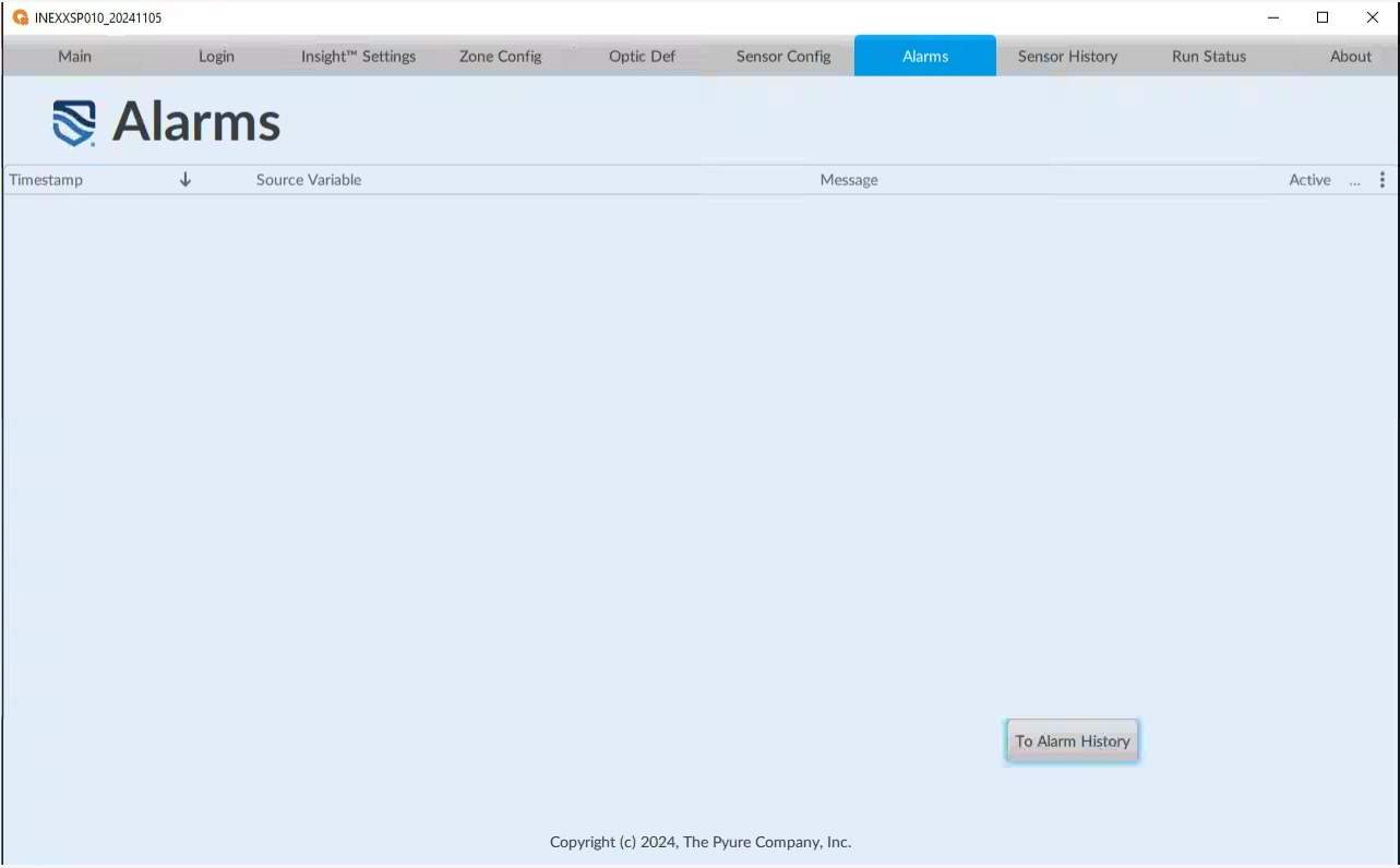
Displays the past alarms with time/date stamps showing when they occurred.
From/To: Allows the User to select the alarm period to be displayed.
Refresh Button: Refreshes the screen once the From/To date and time have been set.
Export Log Button: Saves the alarms to a text file.
To Alarm Acks Button: Navigates to the Active Alarm screen.
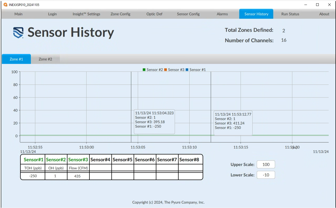
Sensor History Screen
The sensor history screen lets the user display sensor data from the selected zone. Note: This screen is interactive in that the user can scroll through different time periods and change the sensor scale of the graph. The user can also select different points on the graph, which will then display the Date/Time and sensor value(s) of the point selected.
Zone Number Selected: Select the tab for the zone to be displayed/configured.
Total Zones Defined: Displays the total number of zones defined and controlled by the Insight Edge controller.
Number of Channels: Displays the total number of opticmChannels mapped to the selected zone.
Sensor Table:
Sensor #1 - #8: Displays information about the sensors in the selected zone.
Sensor Type: Displays the identity of the sensor type and unit of measure of the mapped sensor in the selected zone.
Value: Displays the value of the sensor
Upper Scale: Sets the upper value of the sensor graph.
Lower Scale: Sets the lower value of the sensor graph.
Run Status Screen
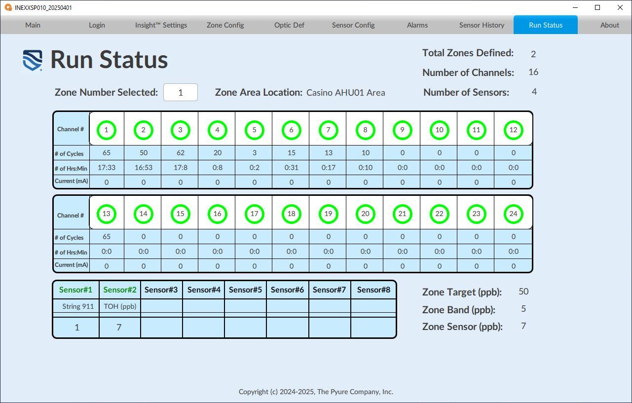
The run status screen lets users display optic and sensor data from a selected zone.
Zone Number Selected: Enter the zone number to display the desired zone.
Total Zones Defined: Displays the total number of zones defined and controlled by the Insight Edge controller.
Number of Channels: Displays the total number of optic channels mapped to the selected zone.
Number of Sensors: Displays the total number of sensors mapped to the selected zone.
Zone Area Location: Displays the documented location of the selected zone.
Optic Channel Tables:
- Channel #: Displays the optic channel number. When the channel # is green, it indicates that the optic channel is active.
- # of Cycles: Displays the number of cycles (ON/OFF) of the optic channel.
- # of Hours:Mins: Displays the number of hours and minutes the optic channel has been active.
- Current (mA): Displays the electrical current in milli-amps of the optic channel.
Sensor Table:
- Sensor #1 - #8: Displays information about the sensors in the selected zone.
- Sensor Type: Displays the identity of the sensor type and unit of measure of the mapped sensor in the selected zone.
- Value: Displays the value of the sensors in the selected zone.
Zone Target (ppb): Displays the control system's target total oxidant level for the selected zone.
Zone Band (ppb): Displays the control band around the control system's target level for the selected zone.
Zone Sensor (ppb): Displays the sensor value the control system uses for the selected zone.
About Screen
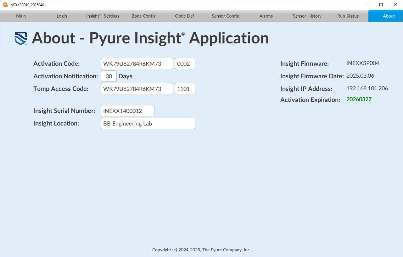
The About screen allows the user to enter various operational information and configuration parameters for the system as follows:
Activation Code: Enter the activation code from Pyure to start the system. If the code is valid, it will show an expiration date in green.
Activation Expiration: Displays the activation expiration date generated by the activation code.
Activation Notification: Specify how many days in advance you want to receive a warning before the activation expires.
Temp Access Code: This temporary activation code is valid for one day. This code allows a user to change various parameters that would typically not be permitted by the USER's permissions.
Insight Serial Number: This should contain the serial number of the Insight Edge controller, which must match the serial number on the controller's product label.
Insight Location: A free-form text field utilized to document and identify the location of the Insight Edge controller.
Insight Edge Firmware: Displays the current firmware version of the Insight Edge controller application.
Insight Firmware Date: Displays the current firmware date of the Insight Edge application.
Insight IP Address: Displays the current IP address of the Insight Edge controller.
Copyright 2025, The Pyure Company
Insight Edge is a trademark of The Pyure Company
Boynton Beach, FL 33426 USA
Document # INEXXLA010
08/19/202

